
Gas Pressure Regulator Selection for Regulating Stations
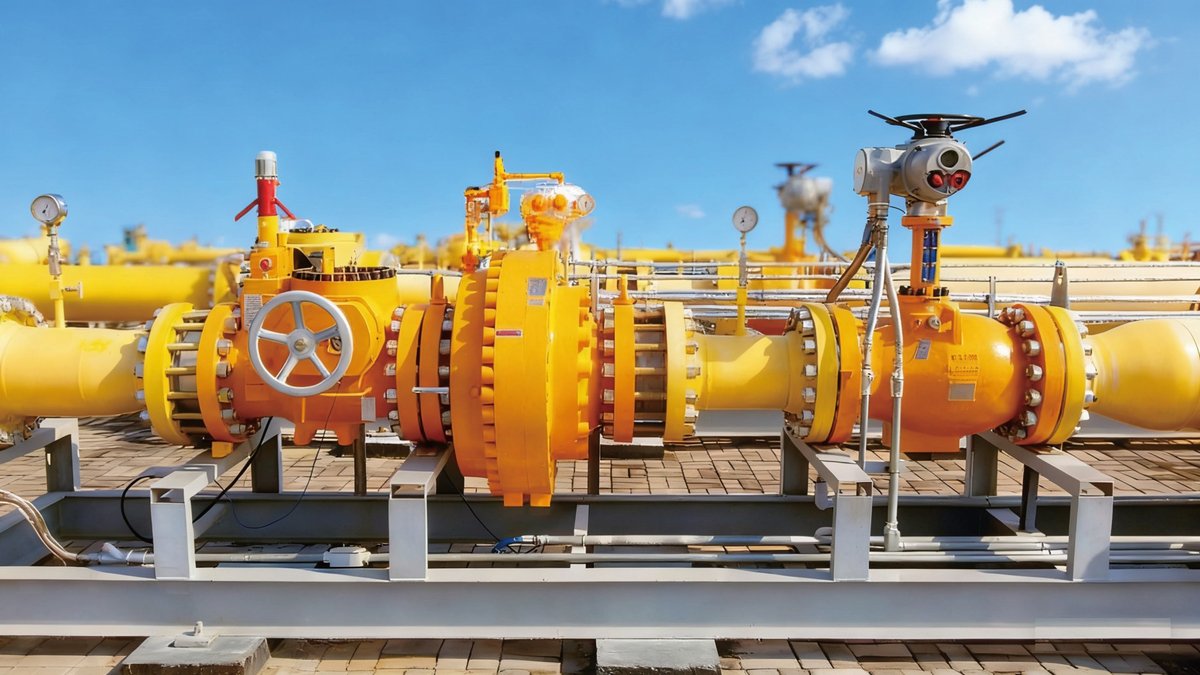
A gas pressure regulator for a regulating station is chosen as part of a train, not on its own: a safety shut-off valve, a monitor regulator and an active regulator in series, each with its own set point. Size the active regulator for the flow and pressure drop, set the monitor to take over if it fails, and set the slam-shut to close if both fail. The data sheet figures that matter are the EN 334 accuracy and lock-up classes for the regulators, and the EN 14382 accuracy group and response time for the shut-off valve.
What a gas pressure regulating station has to do
Every regulating station, from a pipeline offtake to a factory boundary, does the same job: take gas at a variable upstream pressure and deliver it at a stable, lower pressure, without ever letting the downstream system see more pressure than it was designed for.
That gives two separate duties:
- Control: hold outlet pressure within a band across the full flow range, from minimum night load to peak demand.
- Protection: if control is lost, stop the pressure from rising above the downstream design limit.
A single regulator can do the first. It cannot do the second, because the failure you are protecting against is the regulator itself: a torn diaphragm, a blocked pilot, debris under the seat, or ice in the pilot line. Protection therefore comes from additional devices that stay passive in normal operation and act only when control fails.
The typical station sequence in our product documentation is: station inlet, filtration, regulation, metering, outlet. City gas stations add heating ahead of regulation and odorisation before the gas leaves for users, as described for the City Gas Gate Station.
The standard train: slam-shut, monitor, active regulator
The PetroBest Pressure Regulating System is built from a sequence of “safety shut-off valve + monitor regulator + active control valve”, connected from upstream to downstream, in a modular design (PetroBest Equipment Catalogue 2025, p. 12). The catalogue describes how the three devices share the work:
- In normal operation the safety shut-off valve and the monitor regulator stay fully open. The active control valve holds the downstream pressure.
- If the active valve fails and cannot hold outlet pressure, the monitor regulator takes over pressure control.
- If the monitor also fails, the safety shut-off valve closes and cuts off the gas flow.
The same catalogue page lists a second configuration with two safety shut-off valves ahead of the active control valve, and notes that the active control valve can be a regulator or an electric or pneumatic control valve.
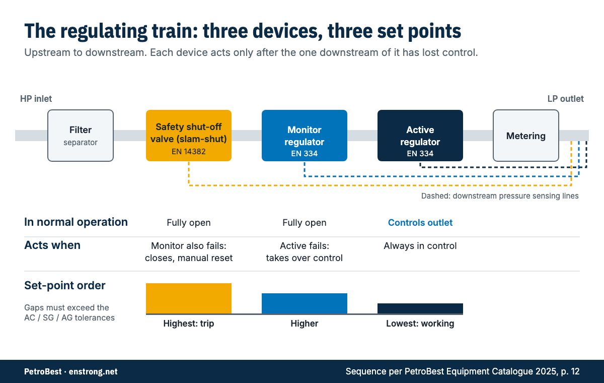
The set-point order is what makes the train work. The active regulator has the lowest set point. The monitor is set a little higher, so it sees outlet pressure below its own set point and stays wide open. The slam-shut trip is set higher again. A relief valve, where fitted, is set between the monitor and the slam-shut to vent small leakages at lock-up without tripping the station. The gaps between these settings have to be larger than the accuracy and lock-up tolerances of the devices below, or the monitor will start to throttle and the slam-shut will trip on normal transients. That is why the data sheet classes in the next section matter.
Stations are commonly built with two such trains in parallel, one duty and one standby, so that a tripped or maintained run does not interrupt supply.
Reading EN 334 and EN 14382 figures on a data sheet
EN 334 covers gas pressure regulators, and EN 14382 covers gas safety shut-off devices, both for inlet pressures up to 100 bar. Both standards define performance classes that appear directly on data sheets.
For regulators (EN 334):
- Accuracy class (AC): the permitted deviation of outlet pressure from set point across the flow and inlet-pressure range. AC1 means the outlet stays within about ±1% of set point.
- Lock-up pressure class (SG): how far outlet pressure may rise above set point when demand drops to zero and the regulator closes. SG2.5 means a lock-up rise within 2.5%.
- Minimum operating differential pressure: the smallest inlet-to-outlet drop at which the regulator can still control. If your inlet pressure can fall close to the outlet set point, for example at the end of a long lateral in winter, check this figure first.
For safety shut-off valves (EN 14382):
- Accuracy group (AG): how precisely the valve trips at its set pressure. AG1 is a trip within about 1% of setting.
- Response time: the time from reaching the trip pressure to full closure.
- Over- and under-pressure trip: most slam-shuts trip on high pressure; some also trip on low pressure, which protects against a burst downstream pipe or loss of supply followed by uncontrolled restart.
The Flowbetter regulators are listed at up to +1% accuracy (AC1) and up to 2.5% lock-up (SG2.5). The shut-off valves are listed at up to +1% over-pressure cutting accuracy (AG1). These are catalogue figures; final data is confirmed per project.
Comparing the Flowbetter regulator and slam-shut range
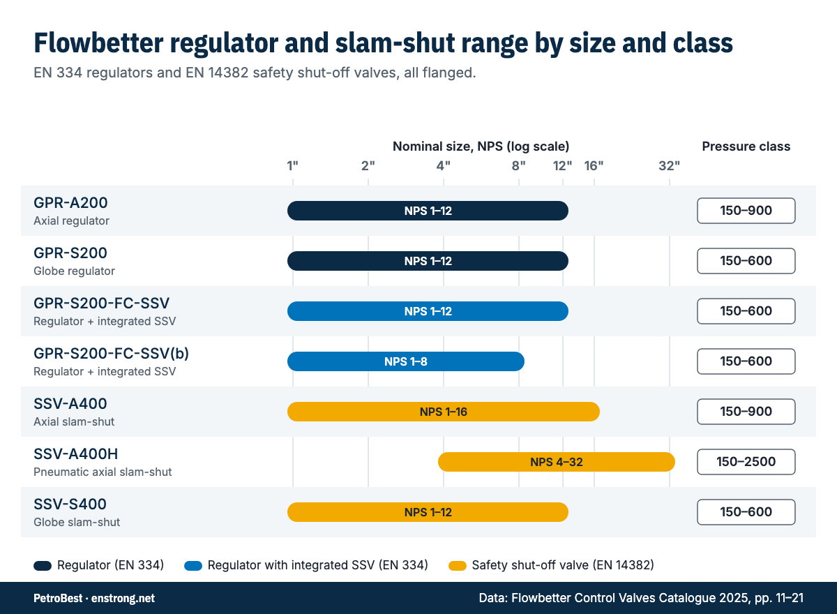
The Flowbetter catalogue groups its station valves into axial type and globe type. The practical differences for selection are the pressure class, body construction, minimum differential pressure and the integration of the shut-off function.
| Model | Function | Size (NPS) | Pressure class | Standard | Key figures | Body |
|---|---|---|---|---|---|---|
| GPR-A200 | Axial regulator | 1–12 | 150–900 | EN 334 | AC1, SG2.5, min. ΔP 0.1 MPa | Forged steel LF2 |
| GPR-S200 | Globe regulator | 1–12 | 150–600 | EN 334 | AC1, SG2.5, min. ΔP 0.05 MPa | Cast steel WCB, LCB |
| GPR-S200-FC-SSV | Regulator with built-in SSV | 1–12 | 150–600 | EN 334 | AC1, SG2.5, AG1, shut-off < 1 s | Cast steel WCB, LCB |
| GPR-S200-FC-SSV(b) | Regulator with built-in SSV | 1–8 | 150–600 | EN 334 | AC1, SG2.5, AG1, shut-off < 1 s | Cast steel WCB, LCB |
| SSV-A400 | Axial slam-shut | 1–16 | 150–900 | EN 14382 | AG1, response < 1 s | Cast steel LCC |
| SSV-A400H | Pneumatic axial slam-shut | 4–32 | 150–2500 | EN 14382 | AG1, response < 2 s | Cast steel LCC |
| SSV-S400 | Globe slam-shut | 1–12 | 150–600 | EN 14382 | AG1, response < 1 s | Cast steel WCB, LCB |
Source: Flowbetter Control Valves Catalogue 2025, pp. 11–21. All models are flanged. Ambient temperature is listed as −73 °C to +70 °C, customisable, for all models except the GPR-S200-FC-SSV(b), for which the catalogue gives no figure.
A few points follow from the table:
- Pressure class decides the family first. Above Class 600, the axial GPR-A200 and SSV-A400 cover up to Class 900. The pneumatic SSV-A400H goes to Class 2500 and to NPS 32, which suits large-bore, high-pressure transmission stations.
- Low differential pressure favours the globe regulator. The GPR-S200 series is listed with a minimum operating differential of 0.05 MPa, against 0.1 MPa for the GPR-A200.
- Integrated or separate shut-off. The GPR-S200-FC-SSV and FC-SSV(b) put the slam-shut into the regulator body. The separate SSV-A400 and SSV-S400 add under-pressure monitoring, remote control and a position transmitter as options.
- Pilot heating. All GPR regulators list an electric pilot heater, an internal noise reducer and a position transmitter as options. Pilot heating is worth specifying wherever a large pressure drop can cool the gas enough to freeze moisture in the pilot line.
Transmission, city gate and industrial supply: what changes
The train is the same across applications. What changes is pressure class, size, how much redundancy the owner requires, and what sits around the regulating runs.
Transmission and compressor stations. High inlet pressure and large bore dominate. The 2025 PetroBest catalogue describes the Pressure Regulating System as used in long-distance pipeline compressor and transmission stations and in city gate stations. Our group project list includes large-bore pressure regulators on the China–Russia East-route Natural Gas Pipeline (2019) and a DN600 Class 900 natural gas pressure control system for Zhongwei Station II on the middle section of the PipeChina West–East Gas Pipeline III (2022).
City gate stations. The City Gas Gate Station performs filtration, heating, pressure regulation, metering and odorisation before gas goes to residential or industrial users. Heating is there because the pressure drop at the gate cools the gas; without it, the regulator body and downstream pipe can ice up. Selection here is usually about a mid-range pressure class, reliable lock-up for low night flows, and a slam-shut on each run.
Industrial and power-plant supply. The Skid-mounted Pressure Reduction Metering Station is designed for gas power plants, fertiliser plants, ceramic, carbon and glass works. Its configuration includes an inlet block valve, filter, shut-off valve, regulator, safety relief valve, flowmeter and outlet block valve, with over-pressure and low-pressure shut-off and gas leak alarm. A regulator with integrated SSV fits well here because it keeps the skid short. A reference from our group list is the RMS fuel gas skid for the BPDB power plant in Bangladesh (2017).
Selection checklist for a gas pressure regulator and slam-shut
Work through these in order. Each step narrows the choice for the next.
- Define the pressure envelope. Maximum and minimum inlet pressure, required outlet pressure, and the maximum allowable pressure of the downstream system. The last figure sets the slam-shut trip.
- Define the flow range. Minimum, normal and maximum flow, including future growth. Size the active regulator so that maximum flow is reached at minimum inlet pressure, and check that it can still control at minimum flow.
- Check the minimum differential pressure. Compare the smallest expected inlet-to-outlet drop with the regulator’s minimum operating differential (0.05 MPa for the GPR-S200 series, 0.1 MPa for the GPR-A200, per the catalogue).
- Choose the pressure class and body material. Match the flange class to the pipeline design pressure, and confirm the body material suits the minimum design temperature.
- Specify accuracy and lock-up. State the required AC and SG classes. Then set the gap between the active and monitor set points wider than the combined tolerance.
- Specify the slam-shut. State the trip pressure, accuracy group, response time, and whether an under-pressure trip is needed. Decide on remote trip and position indication for the SCADA system.
- Decide integrated or separate SSV. Integrated for compact runs; separate where each device must be sized, isolated or replaced independently.
- Check temperature and pilot heating. Estimate the gas temperature after the pressure drop. If it can fall below the hydrate or ice point, specify inlet heating at station level and a pilot heater on the regulator.
- Check noise. Large drops at high flow generate noise; the GPR regulators list an internal noise reducer as an option.
- Decide redundancy. Single run, duty/standby, or two runs at 50% each, plus relief valve and bypass policy.
For the full data sheets, see Downloads.
From valves to a working station
Choosing the valves is half the job. The other half is the station around them: filter separators, heaters, metering, isolation, venting, instrumentation and the control system. The PetroBest regulating and metering skids integrate these functions with the regulating runs, engineered and manufactured to each client’s requirements. Examples in our group profile include the RMS fuel gas skid for the BPDB power plant (2017) and a 42 MPa metering and regulating skid for the Wenjisang Gas Storage project, Tuha Oilfield (2022).
When you send an enquiry, the most useful information is the pressure envelope, flow range, gas composition and temperature, downstream design pressure, required standards and the redundancy philosophy. With those, the regulator, monitor and slam-shut can be selected together, as one train, rather than as three separate purchases.
Questions
What is the difference between an active regulator and a monitor regulator?
The active regulator controls outlet pressure in normal operation. The monitor regulator sits in series with it, set slightly higher, and stays fully open until the active regulator fails to hold pressure. It then takes over control so gas supply continues.
Why does a regulating station need a slam-shut valve if it already has a monitor?
The monitor covers a failure of the active regulator. The slam-shut (safety shut-off valve) covers a failure of both. It closes and stops the flow when downstream pressure reaches its trip setting, and it stays closed until it is reset by hand.
What do AC and SG mean on a regulator data sheet?
They are EN 334 classes. AC is the accuracy class, the permitted band of outlet pressure around the set point. SG is the lock-up pressure class, the permitted rise in outlet pressure above set point when the regulator closes at zero flow. The GPR-S200 is listed with AC1 and SG2.5 in the 2025 Flowbetter catalogue.
What does AG mean for a safety shut-off valve?
AG is the accuracy group under EN 14382: how closely the valve trips at its set pressure. The SSV-A400, SSV-A400H and SSV-S400 are listed at up to +1% (AG1) over-pressure cutting accuracy in the 2025 Flowbetter catalogue.
Should I choose a regulator with an integrated SSV or separate valves?
An integrated unit such as the GPR-S200-FC-SSV saves a flanged body and shortens the run, which suits compact industrial and city gas skids. Separate valves let you size, maintain and replace each device on its own, which is common on larger transmission stations.
Sources
- Flowbetter Control Valves Catalogue 2025, p. 11 (SSV-A400)
- Flowbetter Control Valves Catalogue 2025, p. 12 (SSV-A400H)
- Flowbetter Control Valves Catalogue 2025, p. 13 (GPR-A200)
- Flowbetter Control Valves Catalogue 2025, p. 16 (SSV-S400)
- Flowbetter Control Valves Catalogue 2025, p. 18 (GPR-S200)
- Flowbetter Control Valves Catalogue 2025, p. 20 (GPR-S200-FC-SSV)
- Flowbetter Control Valves Catalogue 2025, p. 21 (GPR-S200-FC-SSV(b))
- PetroBest Equipment Catalogue 2025, p. 12 (Pressure Regulating System)
- PetroBest Equipment Catalogue 2025, p. 16 (City Gas Gate Station)
- PetroBest Group Profile 2026, pp. 30, 32, 33, 35 (project examples)
- EN 334 — Gas pressure regulators for inlet pressures up to 100 bar
- EN 14382 — Gas safety shut-off devices for inlet pressures up to 100 bar