
Slug Catcher Guide: Vessel vs Finger Type, Position and Sizing Data
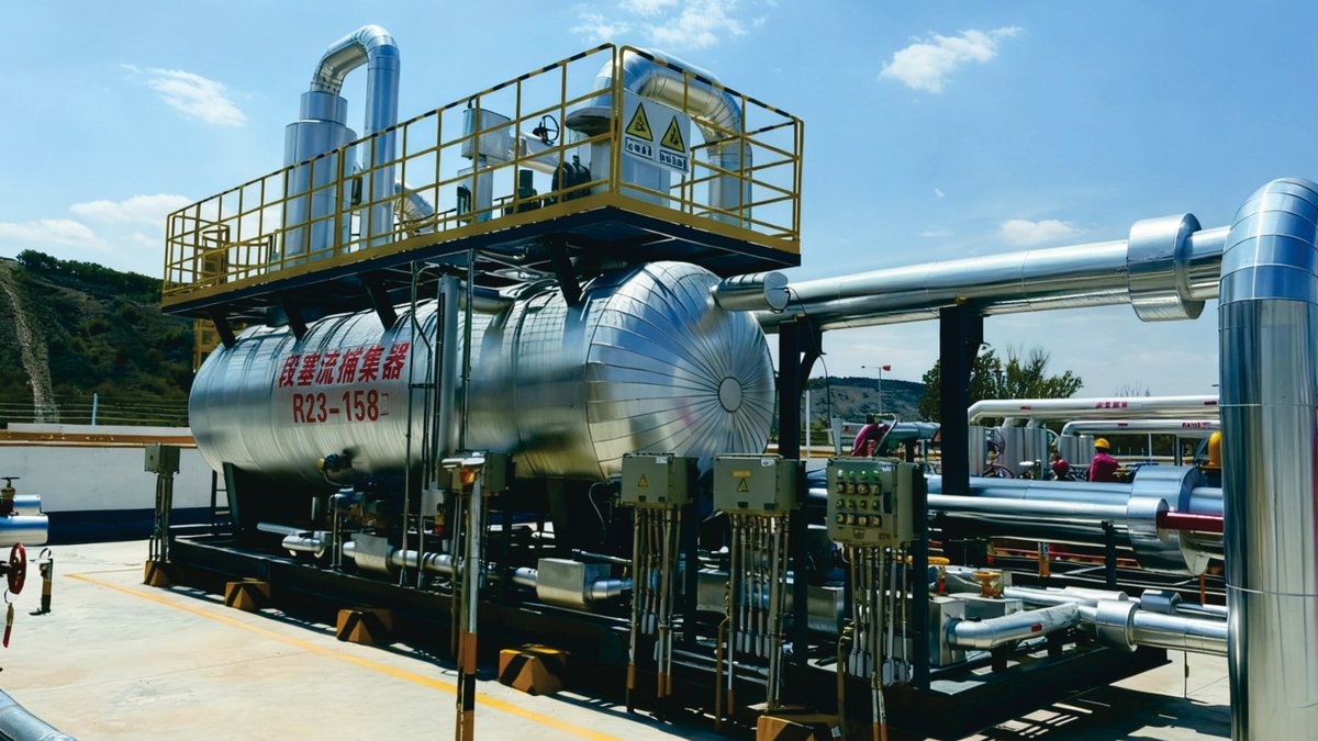
A slug catcher is the first vessel at the end of a multiphase pipeline. It separates gas from liquid and holds the large, intermittent liquid slugs that arrive with the gas, so that equipment downstream receives a steady gas stream and a controlled liquid flow. It comes in two main forms: a single pressure vessel with separation internals, or a finger-type array of parallel pipes built on site.
The PetroBest 2025 equipment catalogue describes our slug catcher as “a key vessel used in oil and gas transmission pipelines to separate and temporarily store intermittent large liquid slugs, ensuring stable operation of downstream equipment”, typically incorporating cyclone separation, vane demisting and wire-mesh demisting elements. This guide explains what that means in practice, how the two design types compare, and what data a supplier needs before a slug catcher can be sized and quoted.
What slug flow is and why it needs a catcher
In a gas pipeline that carries some liquid, whether condensate, produced water or glycol, the liquid does not travel as an even film. It collects in low points, along uphill sections and wherever the gas velocity drops. When enough liquid builds up, it bridges the pipe and is pushed forward as a slug: a plug of liquid followed by a pocket of gas, then another plug.
Slugs form for three common reasons:
- Terrain. Liquid collects in dips and at the foot of risers and is pushed out periodically.
- Flow changes. When the gas rate increases after a shut-in or a turndown, the liquid held up in the line is swept out together, as a surge.
- Pigging. A pig pushes the liquid inventory of the line ahead of it. At the receiving end, this is usually the largest single volume of liquid the station sees.
Without a slug catcher, that liquid arrives at separators, filters, metering runs, compressors or dehydration units designed for gas. Level controllers cannot react fast enough, liquid carries over into the gas outlet, and downstream equipment is exposed to liquid it was not built for. The slug catcher absorbs the surge in one place and releases liquid at a rate the rest of the plant can handle.
Where a slug catcher sits in a gas gathering and transmission train
A slug catcher is located where a multiphase line ends: at the inlet of a gathering station, a central processing facility or a terminal, and downstream of the pig receiver. Upstream of it, wells are usually fitted with a wellhead unit such as a gas production unit, which handles choking, heating, initial separation and metering at the pad. The gathering line then carries gas and remaining liquid to the station.
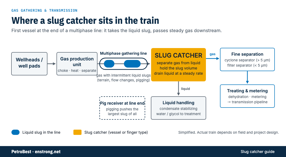
Downstream of the slug catcher, the train typically splits:
- Gas path. The gas goes on to finer separation. In the PetroBest catalogue, a cyclone separator removes particles and droplets larger than 5 µm, and a filter separator removes particles and droplets smaller than 5 µm. At transmission and distribution stations, a gas filtrating separator protects flowmeters, regulators and valves. After that come dehydration, metering and the transmission pipeline.
- Liquid path. The liquid is drained under level control to liquid handling. Hydrocarbon condensate usually goes to stabilization, for example a condensate stabilizing skid; water and glycol go to their own treatment or regeneration.
At smaller gathering stations, the slug-catching duty can be combined with separation and metering in one skid. The separation / metering / gas gathering unit and the gas gathering separator cover gas-liquid separation, liquid collection and metering in gathering systems of gas fields and underground gas storage. Whether a dedicated slug catcher is needed, or a gathering separator with enough liquid volume is sufficient, depends on the slug volume the line can deliver.
Vessel-type vs finger-type slug catchers
There are two main designs. Both do the same job — separate and store — but they are built and scaled differently.
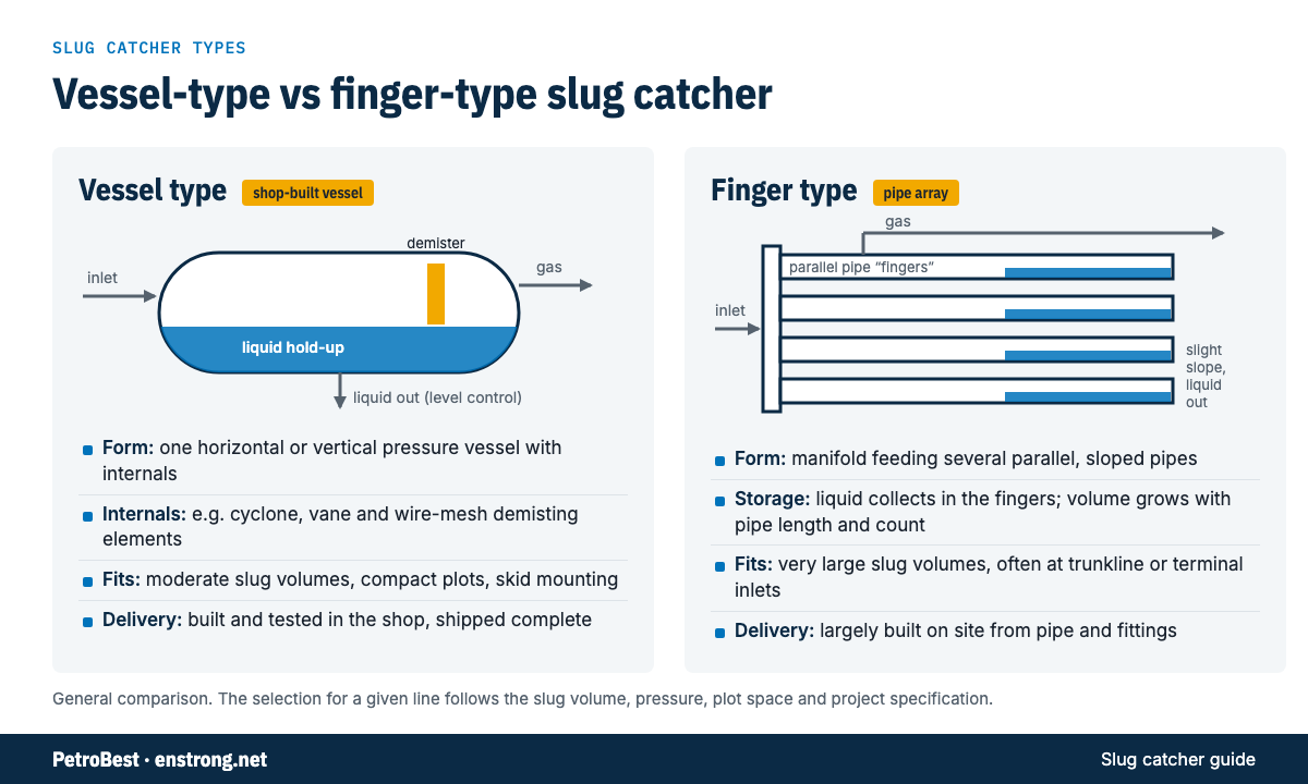
Vessel-type slug catcher. A single horizontal or vertical pressure vessel. The inlet section knocks down the bulk liquid; the liquid collects in the lower part of the vessel, which provides the hold-up volume; the gas passes through demisting internals before it leaves. The unit in the PetroBest catalogue photo is a horizontal vessel mounted on a skid with an operating platform, and the catalogue lists cyclone separation, vane demisting and wire-mesh demisting elements as its typical internals. A vessel is built, inspected and pressure-tested in the shop and shipped as one piece or a small number of skids.
Finger-type slug catcher. An inlet manifold splits the flow into several parallel pipes, the “fingers”, laid with a slight slope. Gas separates in the upper part of each finger and is collected by a gas header; liquid runs down the slope and is stored in the lower section of the fingers before it is drained. Storage volume increases with the number and length of the fingers, so the design scales to large liquid volumes. The fingers are made from line pipe and fittings, and most of the assembly is done on site.
| Criterion | Vessel-type slug catcher | Finger-type slug catcher |
|---|---|---|
| Form | One pressure vessel with separation internals | Manifold plus parallel, sloped pipes and headers |
| Separation | Inlet device, gravity section, demisting internals | Gravity separation along each finger |
| Liquid storage | Lower part of the vessel | Lower section of the fingers |
| Typical slug volume | Small to moderate | Large, such as trunkline pigging slugs |
| Plot space | Compact; can be skid-mounted | Large footprint |
| Fabrication | Shop-built, shop-tested | Mostly field-built from pipe and fittings |
| Wall thickness at high pressure | Governed by vessel diameter | Governed by pipe diameter, so smaller pipe keeps walls thinner |
| Change of capacity later | Add a vessel in parallel | Add fingers if the layout allows |
In short, the vessel type fits gathering stations, wellsite hubs and storage facilities where the slug volume is moderate and a compact, shop-tested unit is preferred. The finger type is chosen where the slug volume is too large for a vessel of practical size, such as at the receiving end of long offshore or onshore trunklines. Some facilities combine both: a finger-type catcher for bulk storage and vessels for fine separation downstream.
What sets the size of a slug catcher
Sizing is driven by liquid, not gas. The main questions are:
- The design slug volume. This is the largest liquid volume the catcher must hold at once. It usually comes from pipeline flow-assurance studies (steady-state and transient multiphase simulation) and covers the worst case among terrain slugging, rate ramp-up and pigging. For most lines, the pigging slug governs.
- The liquid drain rate. A slug catcher does not have to hold the whole slug if part of it can be drained while the slug is arriving. The rate that downstream liquid handling can accept, for example a condensate stabilizer, directly reduces the required storage.
- Control and alarm margins. The storage volume sits between the normal liquid level and the high-level alarm and trip points. These margins add to the net slug volume.
- Gas separation performance. The gas section must separate droplets at the maximum gas rate, at every liquid level the vessel will see. This sets vessel diameter and internals for the vessel type, and finger diameter and length for the finger type.
- Design pressure and temperature. These set wall thickness, material and weight, and for high-pressure lines they often decide between a vessel and a finger arrangement.
Because the design slug volume comes from the pipeline study, the most useful document for a supplier is the flow-assurance report or at least its summary of slug volumes and liquid rates. When this is not yet available, a budget quotation can be made on an assumed volume, which is then confirmed when the study is issued.
Information needed to size and quote a slug catcher
The list below is what we ask for when a slug catcher enquiry comes in. The more of it is available at the start, the fewer rounds of clarification the quotation takes.
- Service and location. Gathering station, processing plant inlet, terminal or storage facility; onshore or offshore; the line the catcher receives (length, diameter, profile if available).
- Gas flow rate. Minimum, normal and maximum, with the units and reference conditions used.
- Liquid flow rates. Condensate, water and any glycol or methanol, for normal operation and for surges.
- Fluid composition. Gas analysis, including H₂S, CO₂ and water content; liquid properties such as density and viscosity; presence of sand or solids.
- Design slug volume. The value, the case it comes from (pigging, ramp-up, terrain) and the source study.
- Pigging details. Pigging frequency, pig type and whether the receiver is part of the scope.
- Downstream liquid capacity. The maximum rate at which liquid can be drained to the next unit.
- Design and operating conditions. Design pressure and temperature, operating range, minimum design metal temperature.
- Preferred type and arrangement. Vessel or finger type, horizontal or vertical, skid-mounted or not, and any plot or weight limits.
- Separation requirements. Required liquid carry-over limit in the outlet gas, and preferred internals if the project has a standard.
- Instrumentation and control. Level measurement, control valves, alarms and trips, safety valves, and whether the control panel is in scope.
- Design code and specifications. The pressure vessel code the project requires (for example ASME Section VIII Division 1 or GB/T 150), project specifications, material requirements and corrosion allowance.
- Inspection and documents. Required NDE, third-party inspection, painting and insulation, and the document list.
- Site conditions. Ambient temperatures, wind and seismic data, hazardous area classification.
- Scope and delivery. What is included (vessel only, skid with piping and valves, pig receiver), required delivery date and delivery terms.
The slug catcher datasheet (the catalogue page) can be downloaded from our downloads page, where the full 2025 catalogues are also available on request. Design code, capacity and scope of supply for each slug catcher are confirmed per project.
What a slug catcher quotation covers
The PetroBest catalogue groups the slug catcher with the other pressure vessels for gas pipelines and stations: gas gathering separators, cyclone and filter separators, pig launchers and receivers, and heaters. For a vessel-type slug catcher, a quotation sets out the vessel orientation, the internals (cyclone, vane and wire-mesh demisting elements, as described in the catalogue), the liquid storage levels and the nozzle list, based on the data in the checklist above.
Where the project also needs downstream separation, metering or liquid handling, the related group products are separation / metering / gas gathering units and condensate stabilizing skids.
Group project references are listed on our projects page. For a slug catcher enquiry, send the data you have; missing items can be completed during clarification.
Questions
What is a slug catcher?
A slug catcher is a vessel or pipe arrangement at the end of a multiphase pipeline that separates gas from liquid and temporarily stores intermittent large liquid slugs, so that downstream equipment receives steady gas and a controlled liquid flow.
What is the difference between a vessel-type and a finger-type slug catcher?
A vessel-type slug catcher is a single pressure vessel with separation internals, built and tested in the shop. A finger-type slug catcher is a manifold feeding several parallel, slightly sloped pipes that store the liquid; it is mostly built on site and is used where the slug volume is very large.
Where is a slug catcher installed?
At the downstream end of a multiphase gathering line or trunkline, typically at the inlet of a gathering station, processing plant or terminal, and downstream of the pig receiver. It is the first separation step before fine separation, treating and metering.
What sets the size of a slug catcher?
The largest liquid volume it must hold, usually the slug pushed ahead of a pig or the liquid surge after a flow increase, together with the rate at which liquid can be drained downstream, the gas flow rate, and the design pressure and temperature.
What information is needed to quote a slug catcher?
Gas and liquid flow rates and compositions, design and operating pressure and temperature, the design slug volume and how it was derived, pigging details, liquid drain capacity downstream, internals and control requirements, design code, material and corrosion allowance, and site conditions.
Sources
- PetroBest Equipment Catalogue 2025, p. 17 (Slug Catcher)
- PetroBest Equipment Catalogue 2025, p. 16 (Cyclone Separator, Filter Separator)
- PetroBest Equipment Catalogue 2025, p. 18 (Gas Gathering Separator)
- enstrong.net product pages: slug-catcher, gas-gathering-separator, cyclone-separator, filter-separator, gas-filtrating-separator, separation-metering-gas-gathering-unit, gas-production-unit, condensate-stabilizing-skid